| HOME | Dyna ST-70 | Dyna PAS-3 | Service & Mods | Downloads | Bookstore |
SP14 preamp 51 build photos
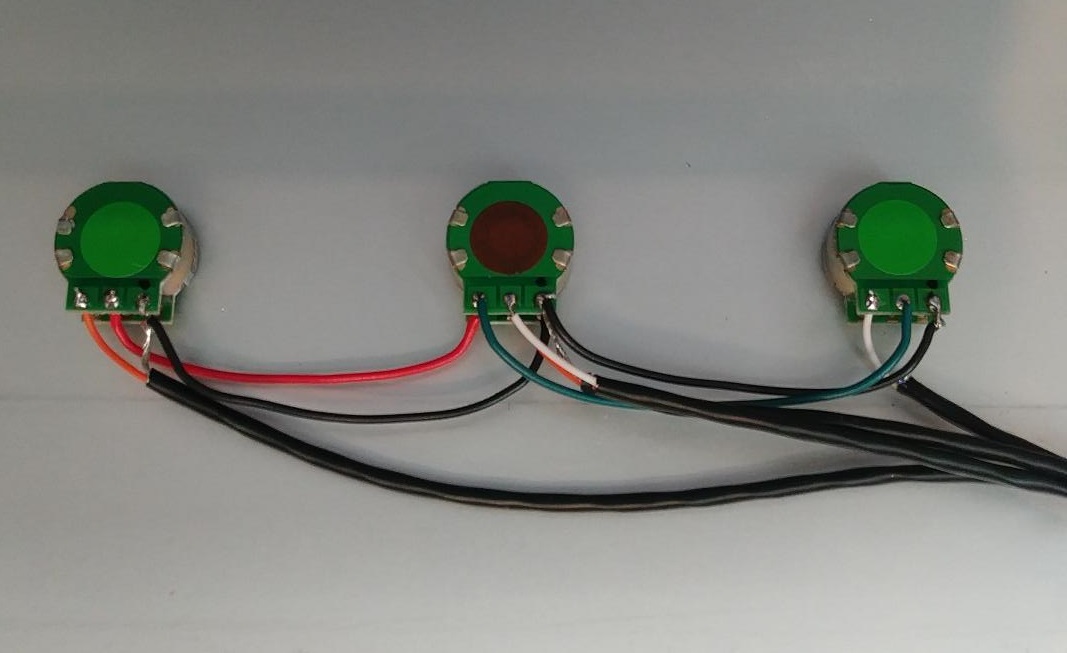
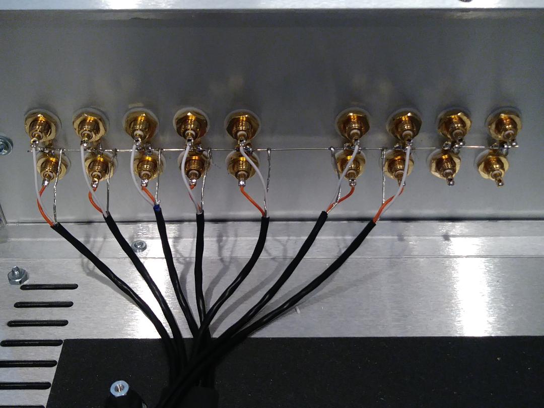
rear of front panel showing right, master, and left attenuator wiring
front rear side, bottom right is ground on each attenuator where shields are connected
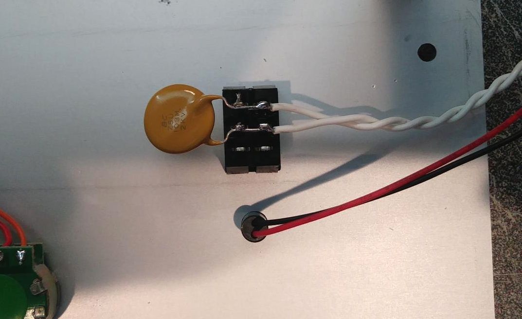
closeup of front panel power switch wiring and suppressor capacitor
red wire on selector is RIGHT output, green wire on selector is LEFT output, both to bottom terminals of TAPE-SOURCE switch white wire is 1st input left channel, orange wire is 1st input right channel (these go to rear panel RCAs)
2nd pair of inputs from selector out to rear panel RCAs (orange right, white left)
3rd pair of inputs from selector out to rear panel
4th and 5th pair of inputs from selector out to rear panel
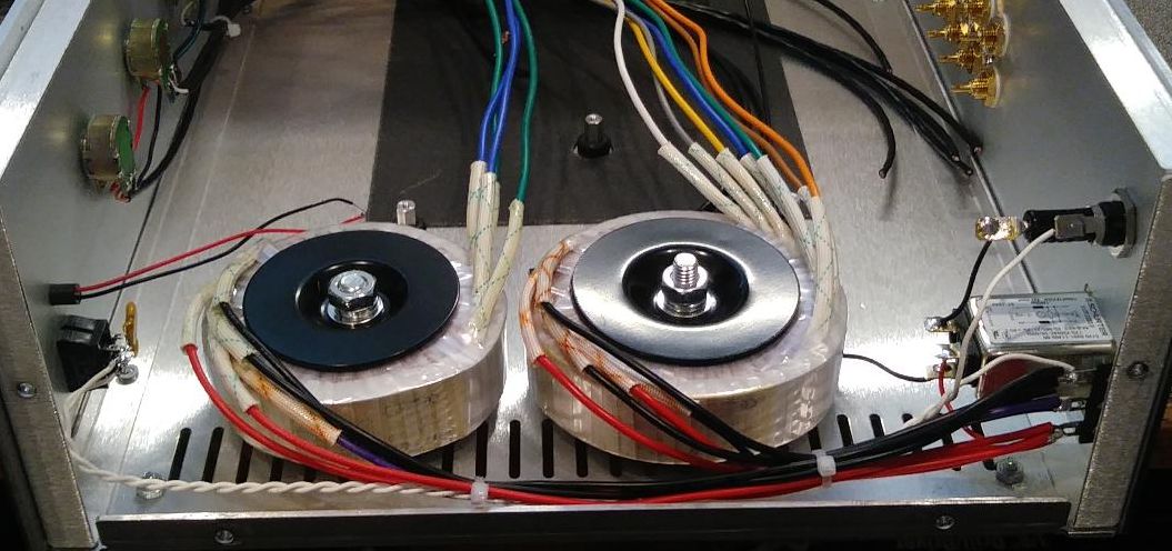
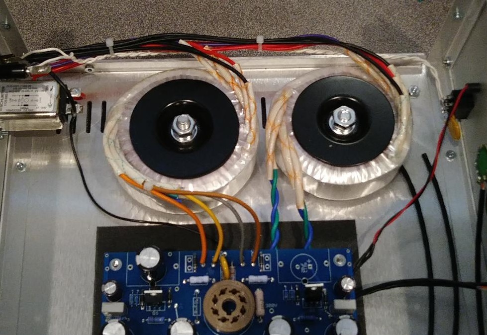
* connect all RED transformer leads to bottom lug of terminal strip next to AC input filter * connect all PURPLE transformer leads to center lug of terminal strip next to AC input filter * connect all BLACK transformer leads to top lug of terminal strip next to AC input filter * take a 32" long white wire and use a drill to tightly twist a pair of wires to run from the front power switch to the rear fuse & terminal strip * use a file to remove oxidation on fuse leads * connect a short red wire from the neutral (N) side of AC input filter to the bottom lug of terminal strip * connect a short black wire from the line (L) side of the AC input filter to the back of the fuse holder * one white wire from front power switch to top lug of terminal strip, the other white wire from front power strip to fuse holder
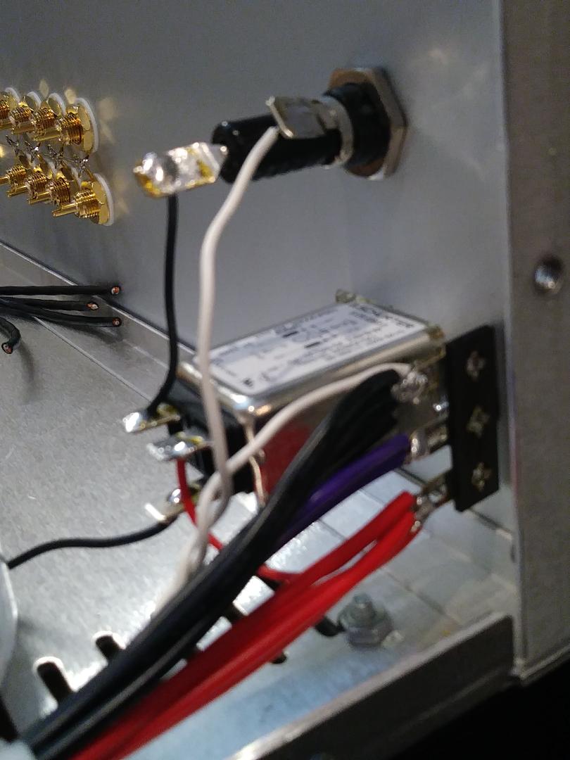
black wire connects left side of AC input to fuse, red wire connects right side of AC input to red wires on terminal strip
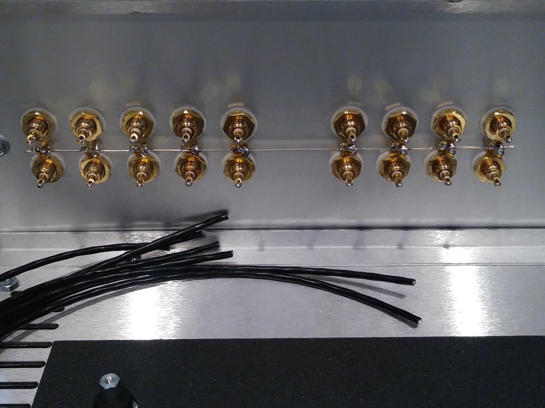
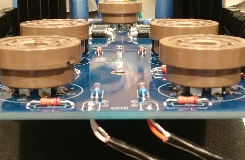
rear panel RCA ground buss
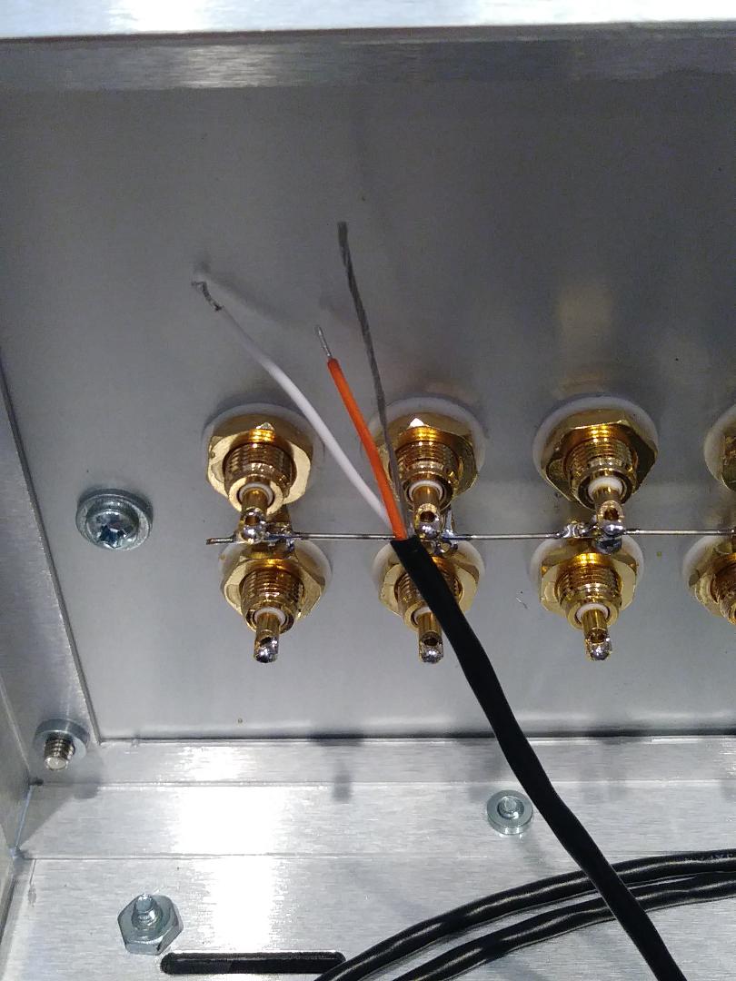
1st input pair from front selector switch, cut orange wire 1/4" than white and ground shield
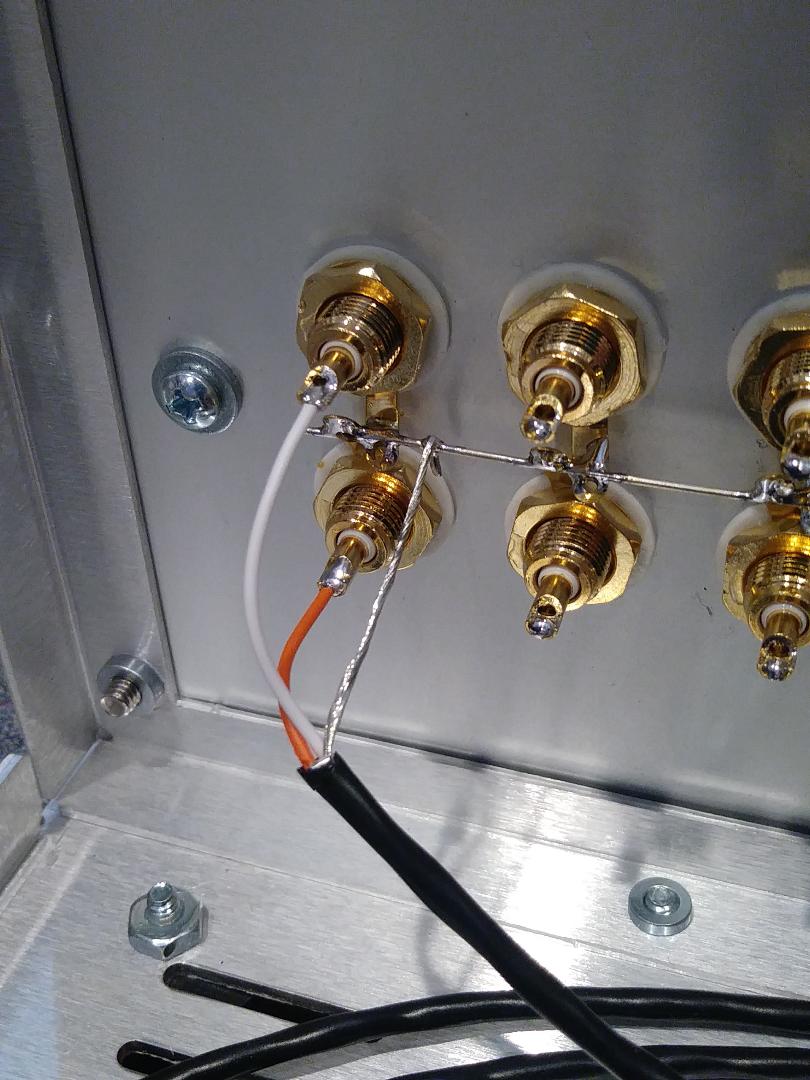
orange to 1st input right, white to 1st input left, and shield to RCA ground buss
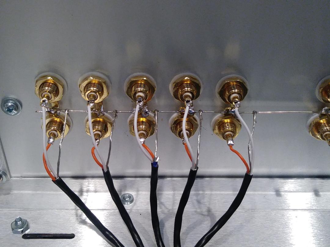
all 5 inputs from front selector to rear RCA jacks and ground buss
TAPE-IN and TAPE-OUT shielded cables connect to rear RCA jacks and ground buss
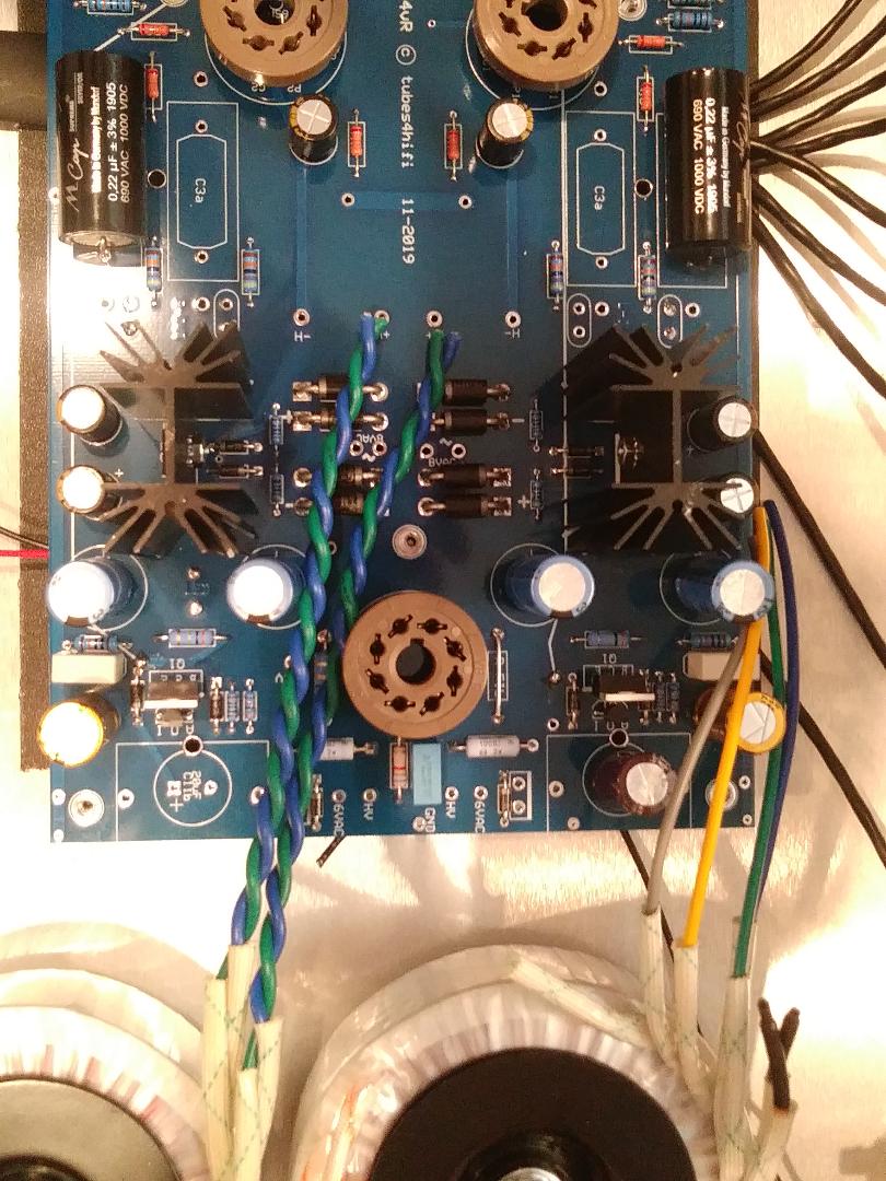
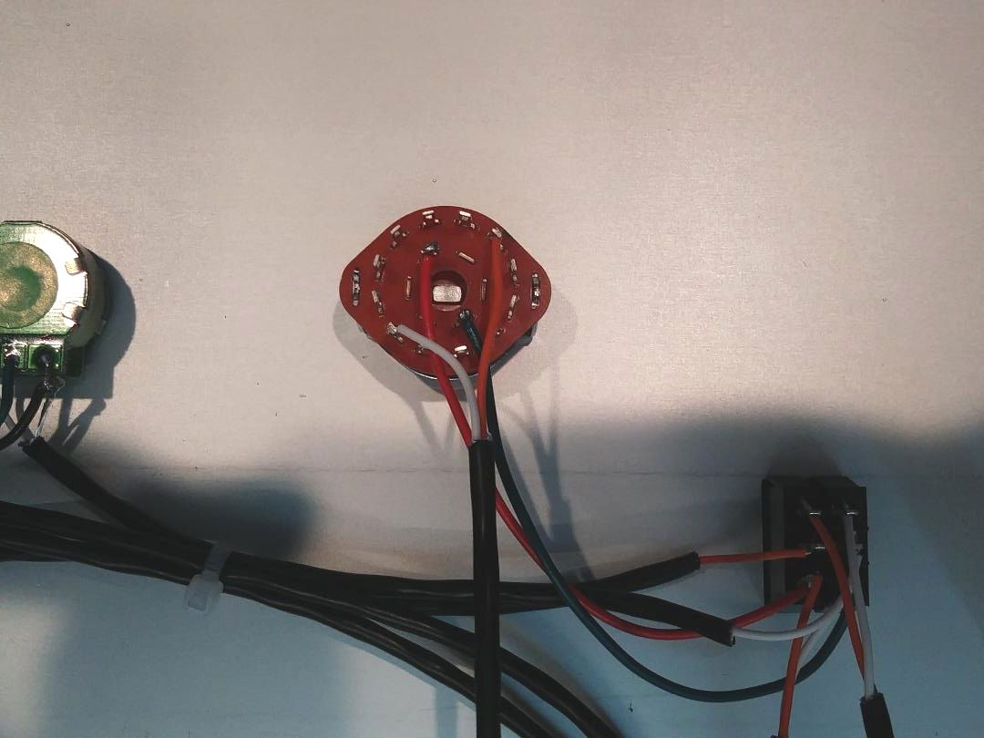
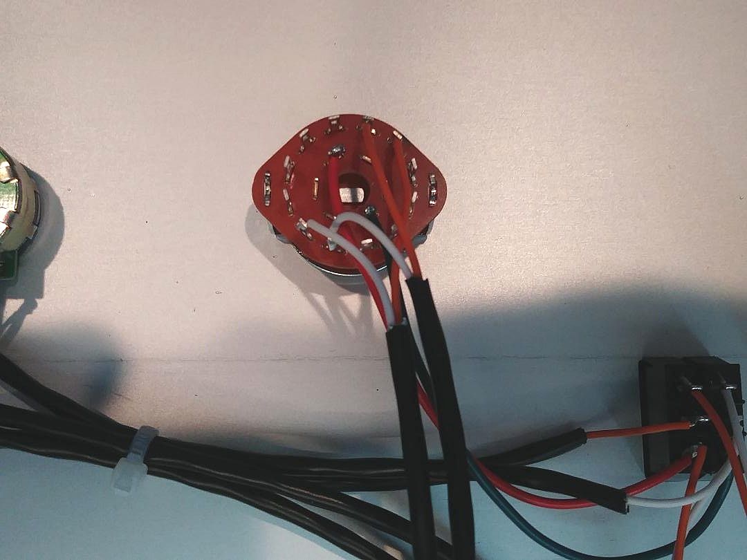
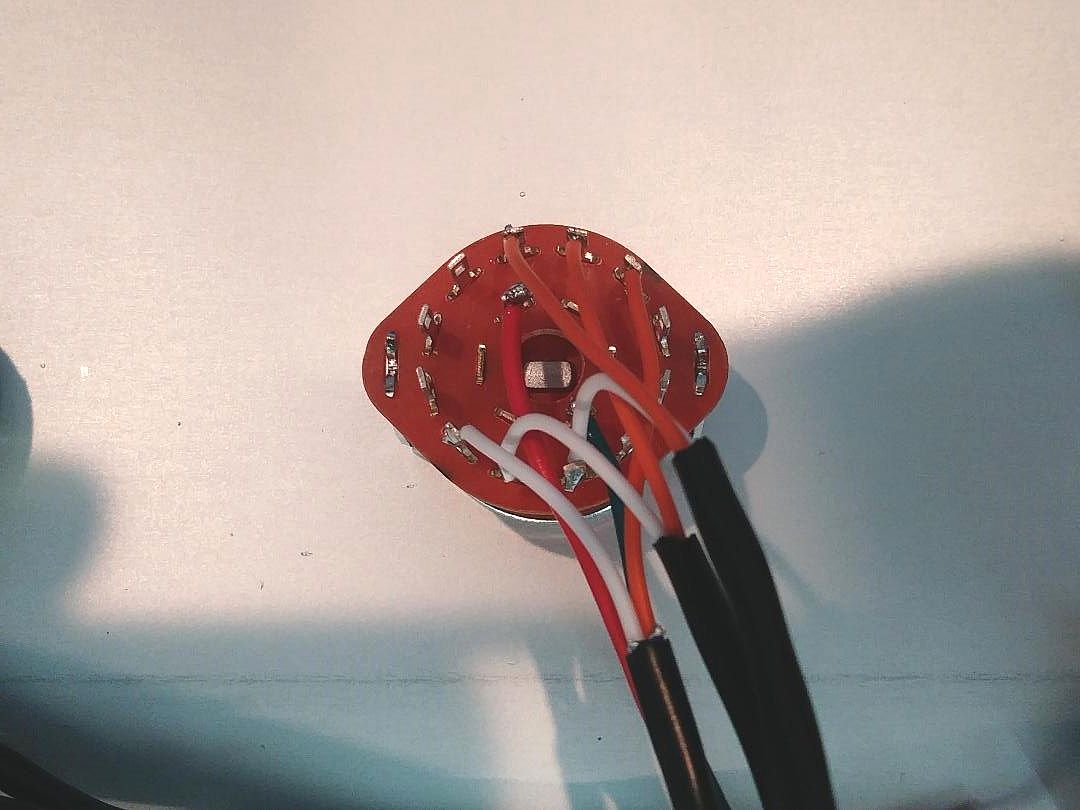
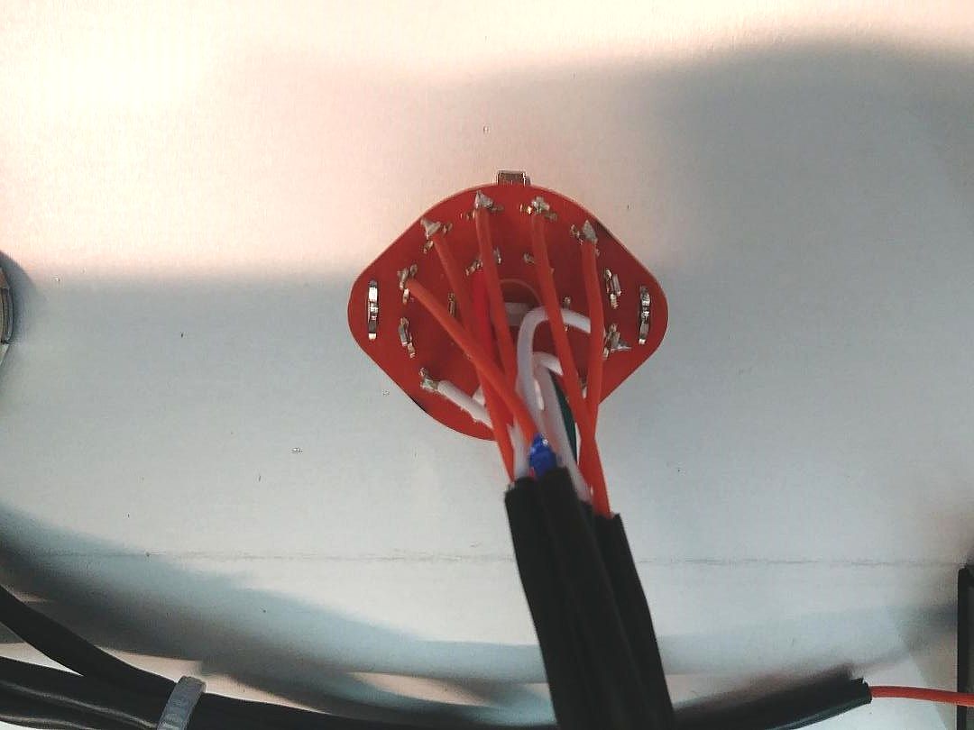
prep transformer wires for connection to PCB, green/blue pairs tightly twisted, cut about 1" longer than needed to route under PCB in next step
orange 6VAC, yellow HV, grey HV, brown 6VAC - connections from power transformer
connect outputs from master attenuator to inputs of PCB (orange, right; white, left) and shield grounds
TAPE IN and TAPE OUT connections are made with coax from front panel SOURCE-TAPE switch
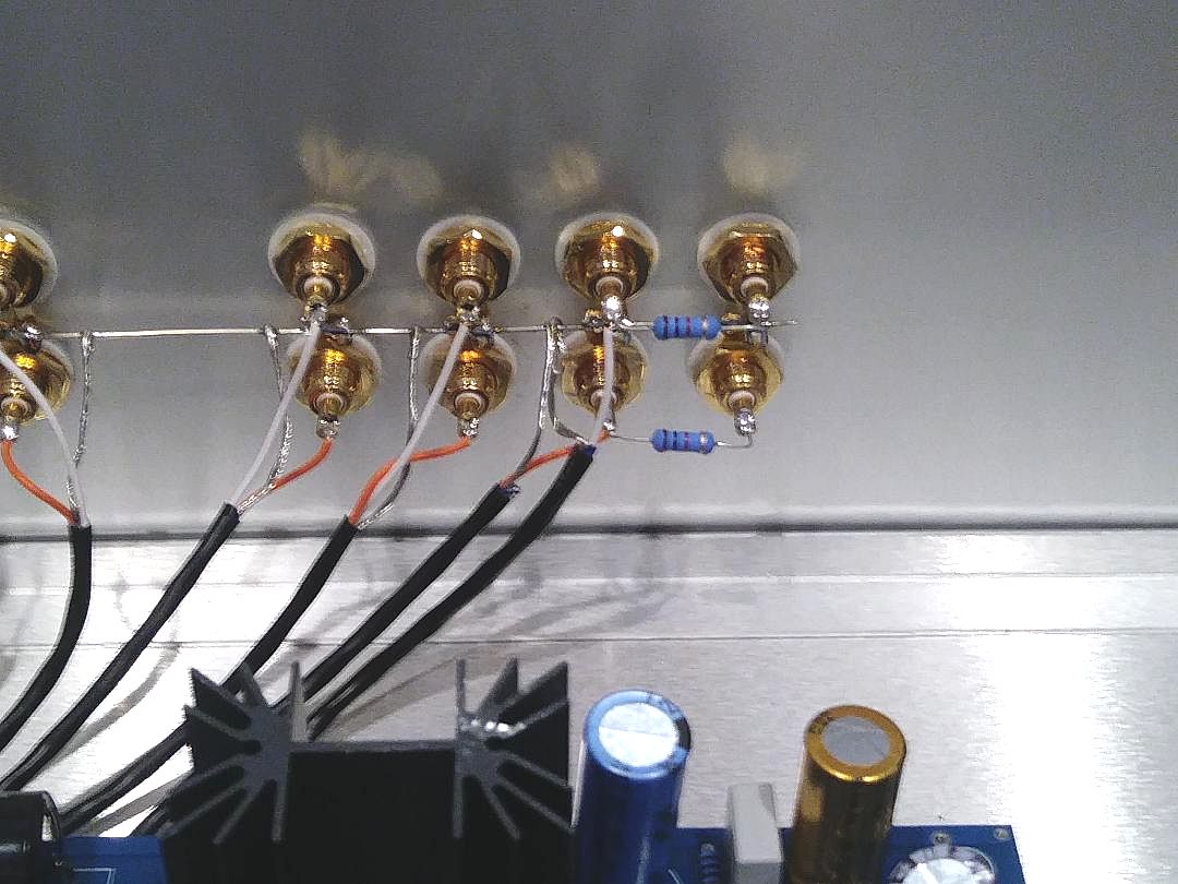
OUTPUT 1 and OUTPUT 2 are bridged together with a 1K resistor, connected from C3 out on PCB, no 2nd pair of output caps (optional)
here are some photos to help you identify the parts to build the SP14
inquire about any other options or modifications you might want via email . . . .
send email to ROY at: info@tubes4hifi.com
|
| |
|
|